A web room for electric and electronics workshop
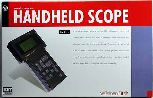
| HANDHELD SCOPE / K7105 |
Please read the notice at the end of this page. This page forbids an unapproved link or reference without my approval from Auction or Business Web Page. |
| No. | 174 | |||||||||||||||||||||||||||||||||||||||||||||||||||||||||||||||||||
| Kit / Parts | Kit | |||||||||||||||||||||||||||||||||||||||||||||||||||||||||||||||||||
| Class. | Measurement | |||||||||||||||||||||||||||||||||||||||||||||||||||||||||||||||||||
| Part Name | K7105 | |||||||||||||||||||||||||||||||||||||||||||||||||||||||||||||||||||
| Shop | Shop : Quality Kits
(http://www.qkits.com/serv/default.asp) Manufacturer : Velleman (http://www.velleman.be) |
|||||||||||||||||||||||||||||||||||||||||||||||||||||||||||||||||||
| Price | Quality Kits price : $250.00 CDN(Canadian dollar) on Dec.15, 2002 $299.99 CDN (Canadian dollar) on Feb.10, 2001 (When I bought it.) |
|||||||||||||||||||||||||||||||||||||||||||||||||||||||||||||||||||
| Main parts | LF357 741 311 74HC4052 4052 TDA8703 VK7105(PIC16C65) | |||||||||||||||||||||||||||||||||||||||||||||||||||||||||||||||||||
| The power supply | 9VDC >200mADC (Option : NiCd Battery) |
|||||||||||||||||||||||||||||||||||||||||||||||||||||||||||||||||||
| Specification |
Table 1 Specification
|
|||||||||||||||||||||||||||||||||||||||||||||||||||||||||||||||||||
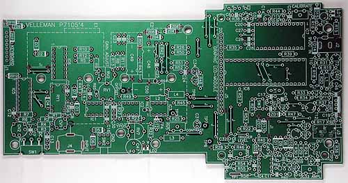
| Print Circuit Board | VELLEMAN P7105'4 | |||||||||||||||||||||||||||||||||||||||||||||||||||||||||||||||||||
| Case | Including a plastic case with an internal shield sheet | |||||||||||||||||||||||||||||||||||||||||||||||||||||||||||||||||||
| Size | 130 x 230 x 43 mm ( 5.1"x 9"x 1.7" ) 600g | |||||||||||||||||||||||||||||||||||||||||||||||||||||||||||||||||||
| Additional parts | Probe , AC Adaptor , 3mm Stereo jack , etc.
|
|||||||||||||||||||||||||||||||||||||||||||||||||||||||||||||||||||
| Comment |
- |
|||||||||||||||||||||||||||||||||||||||||||||||||||||||||||||||||||
| Modify | Software for PC's RS-232C : http://www.velleman.be/download.htm#hhs5 | |||||||||||||||||||||||||||||||||||||||||||||||||||||||||||||||||||
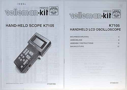
| Example | [ Outline ]
Size 355 x 225 x 73 mm [ Package ]
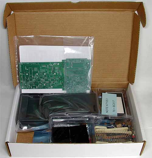
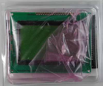
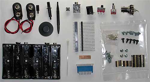
[ Inside of a package ]
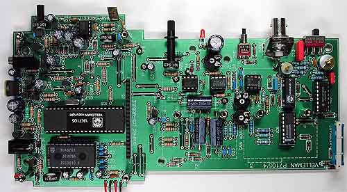
[ A Main printed board ]
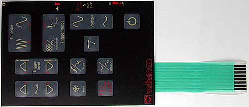
[ Operation key ]
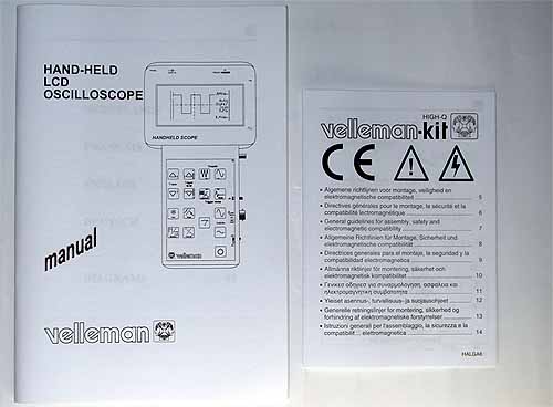
[ Parts list / Assembly procedure document ]
[ Manual / Guideline ]
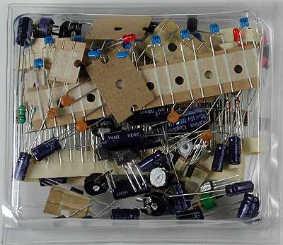
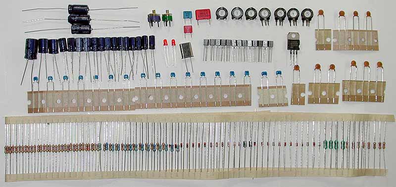
[ Parts of CRs ]
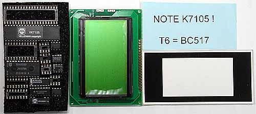
[ Parts of LCD and ICs ]
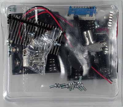
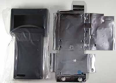
[ Mechanical parts ]
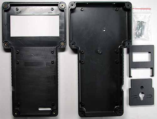
[ Parts of cases ] [ Manufacturing ] This kit (main printed board) is assembled in the order of a parts list.
[ Main board ]
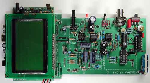
[ Main board with LCD Module ]
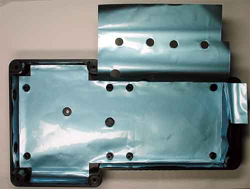
[ Bottom case with the shield sheet ]
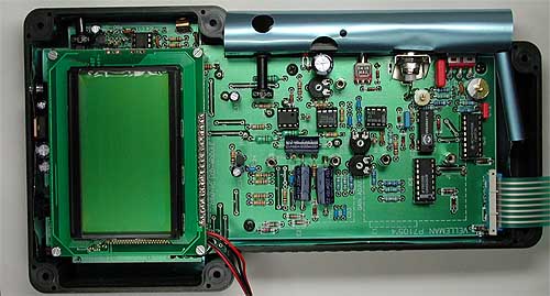
[ Bottom case with the main board and the shield sheet ]
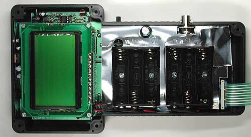
[ Inside view with battery boxes ]
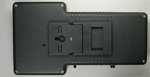
[ Back view with the support parts ]
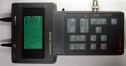
[ Normal operation view that a sine wave is measured. ]
[ Aquision of a PC ] A PC can communicate to this kit by using a downloaded hhs5.zip (201kB) from http://www.velleman.be/download.htm#hhs5. This hhs5.zip contains HHS5.EXE. This HHS5.EXE is the software of an aquision and a waveform display. HANDHELD SCOPE / K7105 is transmitted the measured data to a PC only at once when HANDLE SCOPE / K7105 is turned on. This procedure of an aquition is indicated below.
"Smooth" / "Bar" / "Dot" [ Sample of HHS5.EXE ] HHS5 receives the data which the range of all value are from 0 to 255. I conform the 8 bit resolution. [ My impressions ] Size is small. It is an advantage for me. Don't expect an accuracy. I don't wish to try the making this kit again, because this kit has many parts. |
![]() HANDHELD SCOPE /
K7105 (Japanese Edition)
HANDHELD SCOPE /
K7105 (Japanese Edition)
Special attention
© 1997-2017 Atsushi Itou , JH4CBA , CBA
End of This Page.